

ROUND TUBE CORRUGATION FORMING
Bellows and Corrugated Tube Forming Machine
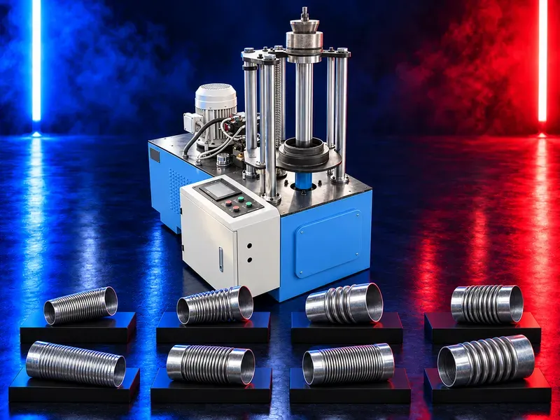
A bellows tube forming machine reshapes a compatible straight round tube into a defined corrugated tube profile. Correct selection depends on the finished corrugation drawing tube diameter and length material thickness seam or weld construction forming method required mechanical performance and downstream connection process.
The prepared round tube is supported and positioned in the forming area where matched tools create the approved corrugation progressively. The process must control profile depth pitch roundness tube length change and surface condition. The term bellows can describe different corrugated geometries and performance requirements. A product drawing and intended duty are therefore required before confirming machine suitability. This machine focuses on corrugated shaping. End flanges or other connection profiles normally require compatible additional tooling or a separate flange forming process verified for the finished tube.
What the machine does
The machine forms a repeated or specified corrugation around a compatible straight round tube. The profile may change tube stiffness flexibility length and external geometry.
The exact product must be defined by an approved drawing rather than the general term bellows.
Input tube requirements
Provide outside and inside diameter length material grade thickness weld or seam type roundness straightness surface finish and end preparation. The input tube must remain within the tolerance required by the tooling.
Dents ovality weld mismatch variable thickness or damaged coating can affect forming consistency.
Corrugation geometry
Specify corrugation pitch depth width radius count formed length transition zones and dimensional tolerances. Define whether the corrugation is continuous local circumferential helical or another approved form.
Confirm the finished overall length and any unformed straight sections required at both ends.
Forming process
The tube is positioned through or around matched forming elements that progressively create the profile. Force travel speed support and sequence should avoid collapse tearing wrinkling or uncontrolled length change.
Verify loading centering forming holding return discharge and fault recovery stages for every approved size group.
Tooling and changeover
Rolls dies mandrels shoes or forming wheels must match the tube and corrugation drawing. Tool clearance surface finish alignment and wear affect profile consistency and tube damage.
Confirm tool identification mounting adjustment changeover handling storage lubrication and replacement limits.
Materials and thickness
Material grade thickness hardness temper weld condition and coating influence forming force springback cracking thinning and surface marking. Carbon steel stainless steel aluminium and other materials require separate verification.
Do not generalize one size or thickness capability across different materials and corrugation profiles.
Tube support and handling
Long thin or large tubes require support during loading forming and unloading to prevent sagging ovality or damage. A mandrel or internal support may be needed depending on the verified process.
Confirm working height support spacing lifting method feed direction finished part removal and safe material routes.
Dimensional and surface quality
Inspect pitch depth profile shape count formed length overall length roundness straightness transitions weld condition cracks thinning wrinkles scratches and coating damage.
Approve the first part after setup size change material batch change tool service adjustment or extended stoppage using approved gauges.
Product performance
Corrugation can affect flexibility stiffness vibration behavior airflow pressure loss fatigue and pressure containment depending on the application. These properties require engineering calculations and product tests outside visual profile inspection.
Machine forming approval does not by itself certify the finished tube for pressure movement fatigue or leakage duty.
End connections and flanging
Leave the required straight end length and dimensional condition for later flanging welding coupling or fitting installation. A dedicated flange rolling process may be preferred for controlled end connection geometry.
Coordinate the corrugation transition with connectors gaskets clamps and installation clearances.
Integration in production
The machine may follow tube rolling welding or seam closing and preparation. Trimming end forming flanging joining leak testing surface treatment and final inspection may follow corrugation.
Maintain traceability of material tube size tooling setup and inspection status through the full route.
Productivity and material use
Accepted output depends on tube size corrugation count formed length material handling setup cycle time inspection and surrounding process capacity.
Measure accepted tubes per shift material yield and changeover time during representative trials instead of relying on general production claims.
Common process risks
Wrong tube size incorrect tools poor alignment insufficient internal support excessive force weld weakness or worn forming surfaces can cause profile variation collapse cracks thinning wrinkles ovality scratches or jams.
Stop production and correct the input tube tooling support or settings when any result falls outside acceptance criteria.
Safety and operator protection
The machine may contain moving dies rollers cylinders rotating parts pinch and crush points stored energy and sharp tube ends. Guards interlocks emergency stops controlled access and energy isolation must follow the approved risk assessment.
Procedures must cover loading centering support trial cycles unloading jam recovery tool adjustment lifting cleaning and maintenance.
Installation and site readiness
Confirm floor capacity leveling anchoring electrical hydraulic or pneumatic services full tube travel support equipment lifting access lighting noise control material flow and maintenance space.
The layout should separate input tubes finished corrugated parts operators tools and rejected parts.
Training maintenance and lifecycle support
Training should cover drawings tube identification tooling references controls support quality checks defect response safe recovery isolation lifting and daily inspection.
Preventive maintenance should address drives cylinders hoses valves bearings shafts guides forming tools mandrels supports sensors guards controls lubrication fasteners and emergency devices. Prepare approved wear parts and spares.
How to select the correct machine
Start with input and finished drawings tube diameters lengths materials thickness weld or seam type corrugation geometry quantities required performance utilities floor plan and handling method.
Selection should confirm forming range tooling force travel support internal support changeover control quality capability guarding maintenance service support and representative sample trials.
Technical information requiring verification
Verify tube diameter and length ranges materials thickness corrugation pitch depth count and formed length ranges seam compatibility tooling forming force cycle time output basis motor power utilities controls accuracy noise dimensions and total weight.
Confirm mandrels supports guards standards installation commissioning training warranty service scope spare tooling parts and dimensional mechanical leakage pressure or fatigue acceptance tests as applicable.
Publishing status
This page describes the machine category forming process and selection logic. Exact sizes thickness profiles materials capacity performance utilities standards and commercial commitments require an approved data sheet drawings and technical review before publication.
Questions we are asked
What is a bellows tube forming machine?
It reshapes a compatible straight round tube into a specified corrugated profile using matched forming tools.
Does the machine form end flanges?
Its primary function is corrugation. End flange capability requires separate compatible tooling or a verified dedicated process.
Can it process every round tube?
No. Diameter length material thickness weld or seam condition and corrugation geometry must match the verified range.
Does forming guarantee pressure or fatigue performance?
No. Mechanical pressure movement leakage and fatigue duties require engineering validation and applicable product tests.
How is corrugation quality checked?
Check pitch depth shape count formed length roundness straightness transitions weld condition thinning cracks wrinkles and surface damage.
What information is needed for selection?
Provide input and finished drawings tube sizes materials thickness seam or weld type quantities performance requirements utilities and representative samples.
Tell us the part you need to make
An engineer reads every request. Usually the same working day.
Related
- Spiral Duct Forming Machine A forming machine for producing round spiral air ducts from compatible metal strip. Machine selection depends on duct diameter, material, strip thickness and width, seam type, cut length, and production target.
- U Shape Automatic Duct Production Line A U shape automatic duct production line converts approved sheet metal coils into prepared duct sections through a coordinated sequence that may include uncoiling leveling beading punching shearing locking flange forming and folding. The correct configuration depends on duct type material thickness dimensions flange system output target and factory layout.
- Automatic Duct Production Line for Rectangular HVAC Ducts An automatic duct production line converts approved sheet metal coils into prepared rectangular HVAC duct blanks and folded sections through a coordinated linear workflow. Depending on the verified configuration it may integrate uncoiling leveling beading punching shearing transfer locking flange forming and folding