

METAL FORMING MACHINES
Metal Lathe Spinning Machine
A metal-forming lathe for producing suitable hollow and rotationally symmetrical components from flat or preformed blanks. Machine selection depends on the material, blank dimensions, thickness, final geometry, tooling, tolerances, and production target.
A metal lathe spinning machine rotates a metal blank against a mandrel while one or more tools or rollers progressively form the material into the required shape. The process is used for suitable round, conical, cylindrical, and other axisymmetric components.
The correct machine must be selected from the finished-part drawing, material, blank diameter and thickness, forming depth, tooling, tolerances, surface requirements, operations, and production quantity. Explore related metal forming machines or send your part for a technical application review.
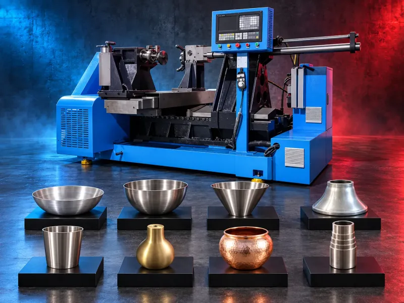
What is a metal lathe spinning machine?
A metal spinning lathe forms a rotating metal blank over a mandrel through controlled pressure from a spinning tool or roller. Material flows progressively into the required rotational geometry rather than being removed through conventional cutting.
Machines may be manual, hydraulic-assisted, programmable, or CNC-controlled. Roller arrangement, force, spindle, axis control, tooling, automation, and supported secondary operations vary by manufacturer and model.
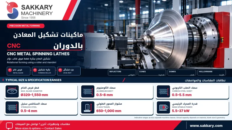
Typical applications
- Horn-shaped and flared components
- Buckets, bowls, cups, and hollow containers
- Conical and tapered components
- Parabolic reflectors and suitable lighting parts
- Cylindrical shells and covers
- Ventilation cones, reducers, and transitions
- Suitable cookware and hollowware components
- Automotive covers and rotational components
- Mechanical housings and industrial shells
- Custom axisymmetric parts produced from approved drawings
Every application must be reviewed against the material, blank condition, dimensions, thickness, forming ratio, geometry, tooling, machine force, and verified working envelope.
How the spinning process works
The blank is clamped against a mandrel and rotated by the spindle. A tool or roller follows a controlled path and applies localized pressure, forming the material progressively over the mandrel through one or more passes.
The result is influenced by material condition, blank design, mandrel geometry, roller profile, forming path, force, feed, spindle speed, lubrication, number of passes, and intermediate heat treatment where required.
Potential production benefits
- Form suitable hollow components from flat or preformed blanks
- Produce repeatable forming paths when programmable control is available
- Reduce dependence on fully manual spinning for repeated parts
- Store and reuse approved programs on compatible machines
- Form components while removing limited material
- Support rough-forming and finishing passes
- Use different mandrels and rollers for approved part families
- Combine compatible secondary operations when the exact model supports them
Production rate, accuracy, wall distribution, finish, setup time, and labor requirements depend on the actual part, material, tooling, machine, program, operator, and quality criteria. They must not be presented as guaranteed outcomes.
Trimming, flanging, and rolling functions
Some metal spinning lathes or integrated production systems may support trimming, flanging, curling, beading, necking, rolling, or turning functions. These operations must be confirmed from the official model catalog, tool layout, axis arrangement, and sample test.
If a function requires a separate station, attachment, or dedicated machine, it must not be described as a standard operation of the spinning lathe.
How to choose the machine
- Provide the finished-part drawing and 3D model where available
- Confirm material grade, temper, and initial condition
- Define blank shape, diameter, thickness, and weight
- Define final diameter, height, depth, and opening
- Identify cones, curves, necks, steps, radii, and flanges
- State dimensional and geometric tolerances
- Define final wall-thickness and surface requirements
- Identify roughing, finishing, trimming, and flanging operations
- Confirm whether intermediate annealing is expected
- Define batch size, product mix, and target output
- Review mandrel, roller, tailstock, and clamping requirements
- Confirm loading, unloading, and automation requirements
- Define inspection and quality-control methods
- Review electrical, hydraulic, lubrication, space, and foundation needs
Technical data to verify
- Manufacturer, brand, model, and country of origin
- Manual, hydraulic-assisted, programmable, or CNC control
- Horizontal or vertical machine architecture
- Single-roller, double-roller, or multi-roller configuration
- Maximum blank diameter, thickness, and weight
- Supported materials and material conditions
- Maximum component diameter, depth, and length
- Spindle speed, power, torque, and interface
- Roller force, travel, speed, and control method
- Controlled axes and axis travels
- Tailstock force, travel, and clamping arrangement
- Maximum mandrel dimensions and tooling weight
- Positioning accuracy, repeatability, and test conditions
- Supported spinning, trimming, flanging, curling, and rolling functions
- Programming software and program-storage functions
- Automatic loading, unloading, and part-handling options
- Hydraulic, lubrication, cooling, guarding, and safety systems
- Dimensions, weight, electrical supply, and foundation requirements
Materials and process trials
Potential materials may include suitable grades of carbon steel, stainless steel, aluminum, copper, brass, and other formable metals. Compatibility depends on alloy, temper, thickness, blank design, forming ratio, heat treatment, lubrication, tooling, and machine capacity.
A sample trial may be required to confirm formability, cracking risk, wrinkling, springback, dimensional accuracy, wall distribution, surface condition, tooling, and production time.
Tooling and mandrel requirements
The mandrel defines the internal geometry of the component. Its material, dimensions, rigidity, surface condition, mounting, and part-removal method must be engineered for the product and production quantity.
Roller profile, clearance, forming path, pressure, lubrication, and number of passes must be selected for the material and geometry. Tooling from another component must not be assumed compatible.
Quality considerations
The production plan should define final dimensions, concentricity, roundness, wall-thickness distribution, surface marks, wrinkles, springback, edge condition, trimming allowance, and inspection method.
The part may require intermediate annealing, trimming, machining, polishing, heat treatment, coating, or another finishing stage depending on the material and finished product.
Limitations and alternative processes
Metal spinning is primarily suited to rotationally symmetrical components. Parts with unsuitable geometry, abrupt transitions, restricted material flow, or demanding wall distribution may require deep drawing, hydroforming, press forming, machining, welding, or another process.
Installation and lifecycle support
Installation planning must consider floor loading, foundation, machine leveling, electrical supply, hydraulic systems, lubrication, tooling storage, blank handling, lifting access, guarding, and operator training.
Installation, commissioning, sample trials, training, maintenance, spare parts, tooling, consumables, software, and warranty scope must be confirmed in the approved technical and commercial offer.
Request an application review
Send the finished-part drawing, material grade, blank diameter and thickness, final dimensions, tolerances, required operations, surface requirements, and production quantity. SAKKARY MACHINERY will review the application before recommending a machine and tooling configuration
Questions we are asked
What is a metal lathe spinning machine?
It is a forming lathe that rotates a metal blank while a tool or roller progressively shapes the material over a mandrel. Which parts can be produced? The process may suit horns, buckets, bowls, cones, parabolic reflectors, covers, shells, and other rotationally symmetrical parts within the verified machine capacity.
Which materials can be formed?
Potential materials include suitable grades of carbon steel, stainless steel, aluminum, copper, and brass. Every grade, thickness, and geometry requires technical review
Can the machine perform trimming and flanging?
Some models support integrated or optional trimming, flanging, curling, rolling, or turning functions. The exact configuration and tooling must be verified.
What information is required for machine selection?
Provide the finished-part drawing, material, blank dimensions, thickness, final geometry, tolerances, required operations, surface requirements, and production quantity.
Tell us the part you need to make
An engineer reads every request. Usually the same working day.
Related
- VICTOR Slant-Bed CNC Lathes Slant-bed CNC turning machines from VICTOR Taichung for machining shafts, bushings, flanges, threaded parts, and other rotational components. The appropriate model is selected according to the workpiece, operations, accuracy, and production requirements.
- CNC Vertical Machining Center (VMC) Vertical CNC machining solutions for milling, drilling, tapping and producing engineered metal components.
- CNC Wire EDM Machines Precision machining solutions for producing complex profiles in electrically conductive materials using a CNC-controlled wire electrode.