

CNC BORING AND MILLING MACHINES
Horizontal CNC Boring Machines
Horizontal CNC boring machines position the spindle on a horizontal axis for controlled boring, drilling, milling, facing, and other supported operations on large or complex components. The correct machine depends on the part geometry, material, bore requirements, working envelope, axes, workholding, accuracy, and required output.
A horizontal CNC boring machine uses programmed axis movement to position the cutting tool and workpiece for machining bores, faces, holes, pockets, and supported features. Depending on the verified design, movement may come from the table, column, spindle head, ram, boring spindle, quill, rotary table, or a combination of these elements. The supplied description identifies a stationary table and a horizontally moving tool. This is one possible arrangement, not a universal definition. Machine configuration, support for long parts, multi side access, chip evacuation, accuracy, and productivity must be confirmed from the approved data for the exact model and application.
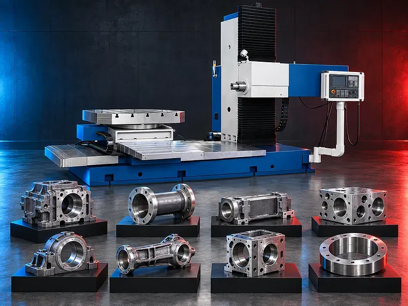
Horizontal CNC boring concept
The horizontal spindle orientation allows a boring tool, drill, milling cutter, facing head, or other compatible tool to approach supported features from the side. CNC control coordinates the machine axes, spindle, feeds, tool offsets, and programmed positions.
The machining result depends on the verified machine geometry, spindle and ram support, tool projection, part rigidity, fixture, thermal condition, cutting data, and inspection method.
Machine configurations and axis movement
Horizontal boring machines may use table type, floor type, planer type, moving column, fixed column, rotary table, or other configurations. The workpiece may remain fixed in some designs, while another design may move or rotate the table during the cycle.
Axis layout, travel directions, simultaneous motion, rotary axes, positioning system, feedback, and control functions must be verified for the exact model.
Boring and hole finishing
Boring enlarges or corrects a prepared hole using a controlled cutting tool. The process may improve diameter, position, straightness, roundness, alignment, or surface condition when the setup and machine capability support the requirement.
Deep or long bores require review of tool support, spindle extension, ram or quill behavior, boring bar diameter, deflection, vibration, chip evacuation, cooling, and measurement access.
Drilling milling facing and tapping
Depending on the verified spindle, control, tooling, and software, the machine may support drilling, milling, facing, counterboring, spot facing, reaming, and tapping in addition to boring.
Each operation requires suitable power, torque, speed, feed, toolholding, axis motion, workholding, cooling, and safety provisions. The page should not promise an operation until it is confirmed for the model.
Multi side machining
A rotary table or suitable axis configuration may allow several sides of a component to be machined with fewer manual repositioning steps. This can preserve datum relationships and reduce handling when the working envelope and fixture support the sequence.
Multi side capability depends on rotary travel, indexing or contouring function, table accuracy, load, part clearance, tool access, cable and fixture interference, and programmed verification.
Large complex and long components
Horizontal boring machines are commonly considered for housings, frames, gearboxes, machine structures, dies, molds, valves, energy equipment, and other components that need controlled bores and faces across a large working envelope.
Pipes, axles, shafts, and other long parts are not automatically suitable. Their support, rotation needs, straightness, overhang, fixture strategy, bore access, and alternative turning or line boring processes must be reviewed.
Spindle ram and quill
The machine may include a main spindle, extendable boring spindle, quill, ram, or a combination according to its construction. Extension can improve access but may reduce rigidity as projection increases.
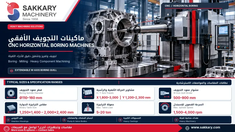
Spindle diameter, taper, speed, torque, power, axial travel, ram section, extension limits, bearings, cooling, and allowable tool load require exact model verification.
Table workholding and load
The fixture should locate the component from controlled datums and resist cutting forces, torque, lifting, vibration, and table acceleration. Clamps and supports must preserve tool access, chip flow, inspection access, and axis clearance.
Table dimensions, slot pattern, rotary function, allowable load, load distribution, center of gravity, indexing accuracy, travel, and collision envelope must be checked before selection.
Tooling tool measurement and compensation
Potential tooling includes boring bars, modular boring heads, facing heads, drills, reamers, mills, taps, holders, extensions, damped tools, and probes compatible with the verified spindle and control.
Tool length, diameter, runout, balance, holder condition, projection, offset data, wear compensation, tool measurement, and tool change limits should be controlled through approved setup procedures.
Chip evacuation and coolant
Horizontal orientation may allow some chips to fall away from certain cutting zones, but effective evacuation is not guaranteed. Internal cavities, deep bores, pockets, fixtures, and long tools can retain chips and interrupt machining.
Coolant pressure and flow, through tool delivery, flushing direction, chip conveyors, filtration, extraction, material behavior, and cleaning access should be selected for the actual process.
Accuracy thermal control and inspection
Acceptance may cover bore diameter, position, straightness, roundness, cylindricity, coaxiality, perpendicularity, face flatness, spacing, surface finish, and relationship between features on several sides.
The result can be affected by geometric condition, axis feedback, spindle extension, table indexing, tool deflection, workholding, material stress, thermal growth, environment, cutting data, and inspection uncertainty.
CNC control programming and simulation
The CNC should support the required axes, work offsets, tool compensation, cycles, rotary functions, data transfer, alarms, diagnostics, and program management for the selected process.
Complex setups should use verified coordinate systems, safe approach planes, tool and fixture models, program review, simulation where available, dry run, and controlled first part approval.
Automation and production flow
Depending on the verified model, options may include automatic tool change, pallet handling, probing, part measurement, tool monitoring, chip management, program networking, and production data collection.
Automation should be selected from the component mix, part weight, setup frequency, batch size, shift pattern, operator availability, inspection method, floor space, and required traceability.
How to choose the correct machine
Provide part drawings and models, material and heat treatment, maximum dimensions and weight, bore diameters and depths, feature positions, sides to machine, tolerances, finish, quantities, batch sizes, fixture concept, and target output.
Selection should review axis travels, spindle center height, table or floor layout, rotary movement, spindle diameter and taper, ram and quill travels, speed, torque, power, table load, tool magazine, probing, cooling, chip control, accuracy tests, utilities, and future work.
Technical information to verify
The approved exact model source must confirm the manufacturer, model, machine configuration, controlled axes, travels, spindle center height, spindle diameter and taper, spindle and ram travels, speed, torque, power, table dimensions, rotary range, allowable load, and tool capacity.
It must also confirm positioning accuracy, repeatability, rotary accuracy, test standard and conditions, CNC system, tool changer, probing, coolant, chip conveyor, electrical supply, compressed air, dimensions, weight, foundation, guarding, software, included equipment, and options.
Safety and operating risks
The risk assessment should cover large moving axes, spindle rotation, tool change, table rotation, crushing and collision zones, tool breakage, hot chips, coolant, heavy fixtures, suspended loads, hydraulic or pneumatic pressure, electrical hazards, stored energy, and maintenance isolation.
Required controls may include full or local guarding, interlocks, emergency stops, collision prevention procedures, lifting plans, secure workholding, safe chip removal, suitable personal protection, training, and documented lockout procedures.
Installation maintenance and lifecycle support
Site planning should cover foundation, floor loading, anchoring, leveling, electrical supply, grounding, compressed air, coolant, chip handling, ventilation, lifting equipment, access, temperature control, network needs, maintenance clearance, and operator and programmer training.
Preventive maintenance should follow approved manufacturer documents for guideways, screws or racks, scales, spindle and ram systems, lubrication, hydraulics, coolant, chip conveyors, tool changer, probes, guards, electrical cabinets, alignment, backups, and calibration.
Limitations and alternatives
A horizontal CNC boring machine can require significant floor space, foundation work, lifting capacity, skilled programming, process engineering, tooling, inspection, and maintenance. It is not automatically the best choice for every long or cylindrical part.
Depending on the component, alternatives may include a horizontal machining center, vertical machining center, floor type boring mill, bridge mill, CNC lathe, mill turn center, line boring system, or dedicated production machine.
Technical review and next step
Send three dimensional models and drawings, material and heat treatment data, bore and feature requirements, datum scheme, tolerances, surface finish, part weight, annual and batch quantities, target output, site utilities, floor plan, and handling method to SAKKARY MACHINERY.
The technical review will compare the application with approved model information and identify the suitable machine layout, travels, spindle and ram configuration, table, tooling, fixtures, inspection plan, automation, installation needs, and any
sample machining requirement.
Questions we are asked
What is a horizontal CNC boring machine?
It is a CNC machine with a horizontally oriented spindle used for supported boring drilling milling facing and related operations on securely fixtured components.
Is the worktable always stationary?
No. Some designs keep the workpiece fixed while others move or rotate the table or use a moving column ram spindle or quill. The exact configuration is model dependent.
Can it machine several sides in one setup?
Potentially yes when a rotary table or suitable axis arrangement provides the required access load capacity clearance and verified positioning performance.
Does horizontal orientation guarantee chip evacuation?
No. Gravity may help in some zones but deep bores pockets fixtures and internal cavities can retain chips. Coolant flushing conveyors and cleaning access must be reviewed.
Is it automatically suitable for pipes shafts and long parts?
No. Long parts require a specific support fixture access deflection and process review. Turning line boring or another machine may be more suitable.
What information is required for selection?
Provide three dimensional models drawings material part size and weight bore requirements datums tolerances surfaces quantities target output utilities floor plan and handling method.
Tell us the part you need to make
An engineer reads every request. Usually the same working day.
Related
- VICTOR Slant-Bed CNC Lathes Slant-bed CNC turning machines from VICTOR Taichung for machining shafts, bushings, flanges, threaded parts, and other rotational components. The appropriate model is selected according to the workpiece, operations, accuracy, and production requirements.
- CNC Vertical Machining Center (VMC) Vertical CNC machining solutions for milling, drilling, tapping and producing engineered metal components.
- CNC Wire EDM Machines Precision machining solutions for producing complex profiles in electrically conductive materials using a CNC-controlled wire electrode.