

HEAVY DUTY TUBE LASER CUTTING
Triple Chuck Heavy Duty Bevel Tube Laser Cutter
A tube laser cutting solution with a three chuck handling concept and bevel cutting capability for suitable heavy pipes and profiles. The correct configuration depends on material, section type, diameter, wall thickness, length, weight, bevel geometry, tolerance, loading, and target output.
A triple chuck tube laser cutter uses three coordinated clamping units to support, position, and move suitable pipes or profiles during cutting. Depending on the verified machine design, the chucks may exchange support roles along the workpiece to control long or heavy material and maintain access to programmed cutting zones. A bevel cutting head can orient the laser beam to produce supported angled edges and weld preparation details in addition to straight cuts, holes, slots, notches, and end profiles. Bevel range, root face, edge quality, collision clearance, and finished accuracy must be confirmed with the exact part and machine.
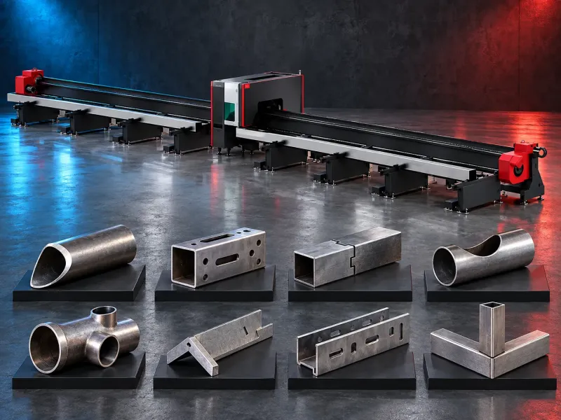
Triple chuck handling concept
The three chucks form a coordinated workholding and feeding system around the tube or profile. Their actual positions, travel sequence, clamping range, load sharing, and exchange logic depend on the machine architecture and control.
A suitable arrangement may provide additional support for long or heavy workpieces and may reduce unsupported span during selected cutting stages. It does not eliminate the need to review straightness, sag, vibration, balance, clamping marks, weld seams, and safe loading.
Heavy duty tube processing
Heavy duty suitability is determined by the verified workpiece diameter or section size, wall thickness, raw length, finished length, weight per piece, total supported load, chuck capacity, support system, drive torque, acceleration, and duty pattern.
The category name alone does not confirm that every large or thick tube can be processed. The exact material and workpiece data must be checked against approved manufacturer limits and a representative cutting trial.
Bevel cutting and weld preparation
Depending on the verified head and axis configuration, the machine may produce supported bevels, angled end cuts, chamfers, compound edge details, and selected weld preparation geometries on compatible tubes and profiles.
Bevel angle, root face, land, kerf position, head access, collision clearance, heat effect, edge quality, dross, and dimensional result depend on the part geometry, material, thickness, process data, support, and calibration.
Suitable tubes and profiles
Potential workpieces may include round tube, square tube, rectangular tube, selected open profiles, and other sections supported by the verified chuck and software configuration.
Each shape requires confirmation of its section range, corner radius, straightness, twist, wall thickness, weld seam, surface condition, clamping method, rotational balance, probing strategy, and cutting head access.
Potential production applications
Potential applications include structural fabrication, construction equipment, agricultural machinery, material handling equipment, vehicle frames, trailers, machinery frames, energy equipment, pressure system components, shipbuilding structures, and general heavy tube fabrication.
Suitability for structural, pressure retaining, lifting, transport, or other safety critical components requires qualified review of the material, design code, weld procedure, inspection plan, traceability, and acceptance criteria.
Supported cutting features
Potential features may include straight and angled end cuts, holes, slots, notches, cope cuts, intersections, locating features, connection details, and bevel preparation where supported by the machine and software.
Every feature must be reviewed for reach, angular range, piercing access, collision risk, support position, chuck interference, thermal movement, tolerance, edge requirement, and downstream assembly or welding.
Material loading support and discharge
Long and heavy material requires a controlled route for storage, lifting, loading, centering, clamping, support, feeding, cutting, finished part discharge, remnant removal, and scrap collection.
Automatic loaders, support rollers, followers, conveyors, cranes, unloading systems, and remnant handling may be available depending on the verified configuration. Their capacities and sequence must match the complete workpiece range.
Accuracy calibration and inspection
Machine positioning accuracy and chuck repeatability do not equal guaranteed finished part accuracy. Results also depend on tube tolerances, ovality, straightness, twist, weld seams, sag, clamping, support, probing, calibration, thermal movement, cutting data, and measurement strategy.
The acceptance plan should define datums, cut length, hole position, angular orientation, bevel geometry, root face, edge condition, dross, heat effect, fit up, traceability, and the inspection equipment used.
Potential production value
A suitable tube laser system may combine length cutting, profiling, holes, slots, notches, intersections, and supported bevel preparation in one programmed route. This may reduce sawing, drilling, coping, milling, manual marking, repositioning, and repeated handling.
Actual productivity, remnant reduction, labor requirement, secondary operation reduction, gas use, cost per part, and return depend on the component mix, nesting, loading, cutting time, inspection, uptime, maintenance, consumables, and downstream operations.
How to choose the correct machine
Provide part drawings and three dimensional models with material grades, tube and profile types, section dimensions, wall thicknesses, raw and finished lengths, weights, weld seams, cut features, bevels, tolerances, quantities, batch sizes, and target output.
Selection should also consider laser power, chuck range, chuck load, axis arrangement, bevel head range, support method, loading and unloading, remnant strategy, probing, software, nesting, cutting gases, extraction, cooling, inspection, and floor space.
Technical information to verify
The approved exact model source must confirm the manufacturer, brand, model, laser source, power, supported materials, tube and profile types, section range, wall thickness range, raw length, finished length, workpiece weight, chuck capacity, and remnant limits.
It must also confirm chuck arrangement, axis travels, bevel angle range, positioning accuracy, repeatability, cutting speed and test conditions, probing, cutting head, collision protection, loaders, supports, unloading, software, extraction, cooling, gases, electrical supply, dimensions, weight, foundation, guarding, and safety systems.
Cutting gases extraction and safety
The process may require oxygen, nitrogen, compressed air, or another approved gas according to the material, thickness, edge requirement, laser source, and qualified cutting data.
The installation must address laser radiation, rotating workpieces, moving chucks, heavy loads, pinch points, falling material, sparks, fumes, dust, fire precautions, barriers, emergency stops, extraction, lifting equipment, and trained operation.
Sample trial and production approval
A representative trial should use the intended material grade, section, wall thickness, length, weight, surface condition, weld seam, drawings, bevels, gas, supports, and acceptance criteria.
Approval may require dimensional inspection, bevel measurement, fit up checks, welding trials, assembly trials, nondestructive testing requirements, cycle review, remnant review, and confirmation of the complete downstream route.
Installation and lifecycle support
Site planning should cover machine footprint, tube storage, material entry and exit, crane or loader access, foundations, electrical supply, grounding, cooling, gases, compressed air, extraction, ventilation, fire precautions, guarding, software connectivity, inspection tools, and operator training.
The exact supply scope, commissioning, training, preventive maintenance, chuck care, optics care, consumables, spare parts, warranty, and service commitments require confirmation in the approved technical and commercial offer.
Limitations and alternative processes
A triple chuck bevel tube laser is not automatically suitable for every profile, material, thickness, length, weight, bevel, tolerance, surface condition, or production volume.
Sawing, drilling, coping, plasma cutting, oxyfuel cutting, robotic cutting, machining, conventional tube laser cutting, or a combined route may be more suitable for some parts. The decision should follow the complete production route and approved trial results.
Technical review and next step
Send the part drawings and tube data with material, section type, dimensions, thickness, length, weight, weld seam, features, bevels, tolerances, quantities, inspection requirements, and target output.
SAKKARY MACHINERY will review the application and identify the required chuck capacity, supports, bevel configuration, loading, software workflow, trial plan, utilities, safety requirements, and information that still requires manufacturer verification.
Questions we are asked
What is a triple chuck tube laser cutter?
It is a tube laser system that uses three coordinated clamping units to support position and move suitable tubes or profiles during programmed cutting.
Why are three chucks used?
A verified three chuck arrangement may provide more controlled support for selected long or heavy workpieces and may allow the chucks to exchange roles during the cutting sequence.
What does bevel cutting add?
Bevel cutting may create supported angled edges and weld preparation details. The available angle geometry root face quality and accuracy depend on the exact head axes software and part.
Which tubes and profiles can be processed?
Potential workpieces may include round square and rectangular tube and selected profiles. Every section range thickness length weight and shape needs model verification.
Can the machine produce zero remnant?
No remnant result should be promised without the exact chuck sequence part layout and manufacturer evidence. Minimum remnant varies with workholding cutting access safety and unloading.
What information is required for selection?
Provide part drawings material section dimensions wall thickness lengths weights weld seams features bevels tolerances quantities inspection requirements and target output.
Tell us the part you need to make
An engineer reads every request. Usually the same working day.
Related
- Fiber Laser Cutting Machines Industrial fiber laser solutions for cutting metal sheets with a configuration selected according to the material, thickness, part dimensions, required cut quality, and production target.
- Integrated Fiber Laser Processing Machine An integrated CNC solution designed to combine compatible sheet-metal operations such as fiber laser cutting, punching, forming, and marking. Actual functions depend on the selected model and configuration.
- Tube Fiber Laser Cutting Machine A fiber laser cutting solution for suitable tubes and metal profiles. Machine selection depends on the material, section type, dimensions, wall thickness, part geometry, cutting requirements, loading method, and production target.