

TOOLS FOR MACHINING AND HOLEMAKING
Cutting Tools for Turning Milling Drilling and Threading
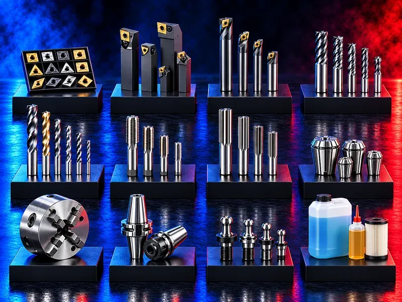
Cutting tools include indexable inserts end mills drills reamers and taps selected to match the workpiece material machining operation machine capability holder coolant strategy and required accuracy. A correct recommendation begins with the application and part drawing rather than the tool name alone.
The right cutting tool supports stable chip formation dimensional control surface quality and predictable production when geometry grade coating cutting data holder and machine conditions work together. This category covers tools for turning milling drilling hole finishing and internal thread production. Each family has different selection inputs wear mechanisms and application limits. Tool dimensions grades coatings speeds feeds tool life availability and performance should be confirmed from approved product data and a documented application review before publication or supply.
Start with the machining application
Define the operation part drawing workpiece material hardness stock allowance machine type spindle interface rigidity coolant and production quantity before selecting a tool.
Required tolerance surface finish cycle time and process reliability should guide the decision.
Indexable inserts
Indexable inserts are replaceable cutting edges used with compatible holders for turning boring grooving threading and some milling operations. Shape size clearance angle chipbreaker grade coating and corner radius must match the cut.
Confirm the complete insert designation and holder pocket compatibility rather than selecting by appearance.
End mills
End mills perform slotting profiling pocketing shoulder milling finishing and three dimensional contouring. Diameter flute count flute length helix geometry corner form material and coating affect chip evacuation rigidity and finish.
Tool overhang should be minimized and the holder runout and spindle condition should suit the required accuracy.
Drills
Drills create holes using solid replaceable tip or indexable designs depending on diameter depth material and machine capability. Point geometry flute design coolant delivery and length to diameter ratio influence centering chip evacuation and tool life.
Define whether the hole is through blind intersecting angled or stacked and whether spot drilling or pilot drilling is allowed.
Reamers
Reamers finish an existing hole to a controlled diameter and surface condition using a small machining allowance. They do not correct every location straightness or severe geometry error left by the previous operation.
Confirm prehole size allowance hole depth tolerance surface finish runout coolant and whether the hole is through or blind.
Taps
Taps produce internal threads by cutting or forming depending on the verified tool and material. Thread standard nominal size pitch tolerance hole depth prehole diameter and blind or through condition are essential selection inputs.
Chip evacuation and reversal strategy are critical for cutting taps while forming taps require a suitable ductile material and a different prehole size.
Workpiece material
Material group exact grade hardness heat treatment scale skin interruptions and abrasiveness influence tool substrate geometry coating and cutting data. General labels such as steel stainless aluminium or cast iron are not sufficient for precise selection.
Provide the material certificate or approved grade whenever possible.
Tool material grade and coating
Carbide high speed steel ceramic cermet cubic boron nitride diamond based materials and other substrates serve different applications. Coatings influence heat resistance friction adhesion and wear behavior.
A premium grade is not automatically the best choice if geometry machine stability and cutting conditions do not match.
Geometry and chip control
Cutting edge preparation rake clearance chipbreaker flute form helix and corner geometry determine how the tool enters the material forms chips and resists load.
Select geometry for the actual depth of cut feed engagement and chip evacuation path rather than the operation name alone.
Holders and machine interface
The insert tool body collet chuck arbor boring bar or tap holder must match the machine interface and tool designation. Runout balance projection rigidity clamping torque and coolant delivery affect performance.
Verify spindle taper turret station shank size available clearance and interference with the part and fixture.
Cutting speed feed and depth
Cutting data should start from the approved tool recommendation and be adjusted for material hardness engagement rigidity coolant overhang and quality target. Machine limits may prevent use of catalog values.
Record validated parameters by operation and avoid presenting one universal speed or feed.
Coolant and lubrication
Dry cutting flood coolant through tool coolant minimum quantity lubrication or tapping fluid may be appropriate depending on the tool material process and workpiece. Concentration pressure flow filtration and direction affect heat and chip evacuation.
Confirm chemical compatibility with the workpiece tool coating machine and downstream cleaning requirements.
Accuracy and surface finish
Tool selection must account for tolerance surface roughness size stability runout deflection edge wear and thermal behavior. Finishing requirements may need a separate tool or dedicated pass.
Measure the part with a suitable method and separate tool error from machine fixture and workpiece effects.
Tool wear and failure analysis
Flank wear crater wear chipping built up edge thermal cracking notching deformation and breakage have different causes. Changing only the grade may not solve instability caused by poor clamping runout vibration or chip recutting.
Record wear location cutting time parameters and part condition before changing the process.
Productivity and tool life
The best economic choice balances cycle time accepted parts edge life changeover predictability scrap risk and machine utilization. Maximum tool life or maximum speed alone may not minimize cost per accepted part.
Compare alternatives using controlled trials and verified local cost inputs.
Inventory and standardisation
Standardising proven tool families holders screws collets and spare parts can reduce setup errors and inventory complexity. Standardisation should not force an unsuitable tool into a critical operation.
Maintain clear item codes compatible holder records minimum stock and controlled replacement rules.
Application trials and approval
Trials should use representative material machine setup coolant fixture and part features. Define success criteria before testing and change one main variable at a time where practical.
Approve the selected tool cutting data inspection method and replacement limit in the process record.
Safety and handling
Cutting tools have sharp edges and can eject hot chips or break under load. Guards chip control correct tightening personal protection and safe tool handling must follow the machine and workplace risk assessment.
Isolate the machine before tool changes and use approved torque tools handling aids and disposal containers.
Information needed for a technical recommendation
Provide the part drawing operation description workpiece grade hardness machine model spindle or turret interface holder data coolant hole or feature dimensions tolerance finish quantity current tool cutting data and observed problem.
Photos of wear and chips and a sample part can improve diagnosis but do not replace verified dimensions and process data.
Technical information requiring verification
Verify tool type designation dimensions substrate grade coating geometry compatible holders screws and spare parts material groups cutting data coolant requirements maximum operating limits accuracy standards and packaging quantity.
Confirm availability pricing delivery warranty return conditions technical support and trial responsibilities from approved commercial and technical sources.
Publishing status
This page describes cutting tool families and selection logic. Exact products dimensions grades coatings performance cutting data standards availability prices and commercial commitments require approved catalogues application review and technical confirmation before publication.
Questions we are asked
Which cutting tool do I need?
Selection depends on the operation workpiece material dimensions tolerance machine interface coolant and production target. Provide the part drawing and process data.
What is the difference between a drill and a reamer?
A drill creates the hole while a reamer finishes an existing hole with a small allowance to improve size and surface condition.
How do I select an insert?
Match the complete insert designation shape size clearance chipbreaker grade coating and corner radius to the holder material and cutting conditions.
Which tap should I use for a blind hole?
The correct tap depends on thread standard depth prehole material chip evacuation and machine cycle. Blind holes need controlled chip space and bottom clearance.
Can one tool cut every material?
No. Tool substrate coating geometry and cutting data must be matched to the exact material grade hardness and operation.
What information is needed for a recommendation?
Provide the drawing material hardness machine interface holder coolant feature dimensions tolerance quantity current parameters and the problem to solve.
Tell us the part you need to make
An engineer reads every request. Usually the same working day.
Related
- Fiber Laser Cutting Consumables & Accessories Essential consumables and cutting-head accessories for fiber laser cutting machines - selected according to the cutting head, machine configuration and application.
- Laser Marking Accessories & Components Lenses, protective components, fixtures and marking accessories for laser marking systems - selected according to the laser source, marking head, workpiece and application.
- Laser Welding Consumables & Accessories Essential consumables and accessories for laser welding systems - selected according to the welding head, machine configuration and application.